23 - Heat Pumps – Type F or Type B RCDs?
BS7671:2018 Amd 2 Heat Pumps – Type F or Type B RCDs?
Inverter speed controlled pumps and compressors circuits require specific Types of RCD. Refer to BS7671 Amd. 2 for the basic requirements, relating to the use of RCDs – where and when e.g. Regulation 411 for automatic disconnection of the supply.
Regulation 531.3.3 covers Types of RCD. The characteristics of the equipment will determine if you require Type F or Type B RCDs and any associated restrictions on RCD sensitivity. Check with the Manufacturer of the standalone heat pump equipment before quoting for the installation.
Equipment design characteristics and installation design
Appropriate planning at the quotation stage saves time and unforeseen expenses on site at a later date. The installation design, equipment to be connected and any RCD requirements including the “Type” and “Sensitivity” must be considered together, not in isolation. Equipment may be self-contained for small installations or have separate units with stand-alone inverter drives for larger installations. Inverter based equipment connected to 3 phase supplies, that does not include an isolating transformer (see Manufacturer’s information), can only be used with type B RCDs see BS 7671 531.3.3. This is explained in detail in Doepke Techpub 17
For single phase equipment, the use of Type F or B RCDs is governed by the level of smooth dc residual current produced under certain fault conditions. Some examples of basic configurations for different inverter topologies (Power Electronic Control System - PECS), and the associated Types of RCD are listed in BS 7671 Figure A53.1. The level of smooth dc fault current is related to the value of the “dc link voltage” (see page 2) i.e. it is function of the original equipment design and can only be defined by the inverter manufacturer.
The ac operational leakage current (PE current), must be compatible with the installation design and the RCD sensitivity. Consider the possible addition of leakage currents, when adding new equipment to an existing installation, as this may require sub-division of existing circuits - see 531.3.2 (i).
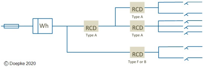
Type F or B RCDs must not be installed downstream of existing Type AC or A RCDs.
DC link voltage determines the Type of RCD
The use of Type F or Type B RCDs for inverters connected to a single phase supply, is governed by the value of smooth dc residual current produced under fault conditions i.e. dc fault = link voltage / fault resistance.
Figure 1 gives a generic example of a single phase combined compressor and fan unit. The dc voltage output from the rectifier will be a minimum of 1.41 x the ac rms voltage. There may be a step-up voltage section, to increase the dc voltage before it is fed into the control section, based on the characteristics of the motors connected to the inverter output. A capacitor connected across the dc bus provides smoothing and a power reservoir, for the control section during the non-conducting period of the AC supply. These characteristics of the inverter design determine the maximum value of smooth dc residual current.
A fault to earth on the dc link section, results in a smooth dc residual current flowing in the PE conductor, back to the source earth and returning via the line conductors through any upstream RCDs.
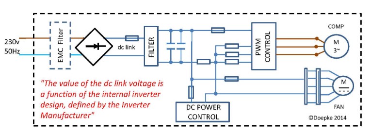
Figure 1: Typical internal control schematic for single phase unit with fan compressor motor
A fault to earth on the dc link section, results in a smooth dc residual current flowing in the PE conductor, back to the source earth and returning via the line conductors through any upstream RCDs.
For smooth dc residual current < 10 mA (defined by the manufacturer), you can use Type F RCDs – see BS7671 531.3.3 (iii) Note 2. For smooth dc residual current > 10 mA or if the manufacturer does not specify the Type of RCD, 531.3.3 (iv) Note 3 refers to the use of type B RCDs.
Power Drive System (PDS) - RCD sensitivity
The manufacturer of self-contained equipment is responsible for testing and providing information on the operational AC leakage current (current flowing in the PE conductor). For standalone inverter drives, providing you use motors, filters and inverters from a reputable company, they should be able to provide levels of leakage current, based on bench tests with fixed lengths of motor cable (normally 5 or 10 meters). These tests are also required to confirm EMC levels. If you are not using a Manufacturer’s recommended set up or you purchase separate components, you are responsible for testing the equipment.
The operational leakage current is governed by the individual elements of the PDS, the design and the associated environment. For the PDS this includes characteristics of external or internal filters, the inverter design and settings. The internal layout of power cables within the machine or control panel. The length of the cable between the output of the inverter, the type of cable and the earthing / screen connections and the motor characteristics. The associated environment includes the existing supply quality and any fluctuations, site harmonics and ambient conditions.
To achieve reliable operation of the equipment, BS 7671 531.3.2 (iii) recognises the need to make allowances for local site conditions. The increasing use of equipment with nonlinear load characteristics and local generation of green energy etc creates additional harmonics and can be an issue when adding inverter based equipment to an existing installation i.e. unwanted tripping of RCDs. Consequently, 531.3.2 (iii) states that the total operational leakage current should not exceed 30% of the associated RCD sensitivity. This allows a safety margin for the effect of normally accepted levels of harmonics and supply voltage tolerances.
BS7671:2018 Amd 2 Heat Pumps – Type F or Type B RCDs?
Type F and Type B RCDs are designed to respond to the sum of the leakage / residual currents generated at various frequencies by any inverter controlled equipment, unlike Type A RCDs which are calibrated on the bases of a 50Hz current.
Always check with the inverter manufacturer, before making a decision on RCD sensitivity.
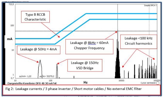
Figure 2 gives an example of the various leakage currents and frequencies associated with a three phase 6 pulse inverter (for simplicity). The leakage current has several main components: a value at 50Hz, regularly quoted in installation manuals for the method of connection and PE requirements . A relatively low value (4 mA in this example) when compared with the leakage current component at the chopper frequency, in this case 60 mA at 8 kHz.
Due to the complexity of these leakage currents (arithmetic sum of all leakage current at all frequencies), for reliable operation, Type F & B RCD sensitivity should not be based just on the 50Hz leakage current component. Refer to the Equipment Manufacturer’s installation manuals for advice on minimum RCD sensitivity requirements. If it is not in the manual, ask the supplier to provide this information before you purchase the equipment and any associated RCDs.
Operational leakage currents
BS7671 543.7.1 places limits on the operational leakage current, based on the method of connection: Check the HP manufactures installation instructions for the correct method of connection and earthing.
Note the requirements of Regulation 543.7.1.202 for equipment with leakage currents > 10 mA method of connection and 543.7.1.203 sizing and connection of PE conductors. This equipment may not be compatible with the appropriate Type of 30 mA RCD. Relatively small inverter setups designed for permanent connection to the supply, may require a minimum of 300 mA RCDs. Check with the manufacturer first, do not leave it until you get to site.
Chaz Andrews – Technical Manager, Doepke UK Ltd
SOURCE: © 2022 - 2024 Chaz Andrews. All Rights Reserved. Doepke Tec Art 23 Heat Pumps RCDs Type F or B v2 Apr.2022