Mode 4 EV (DC) charging: AC side RCD selection
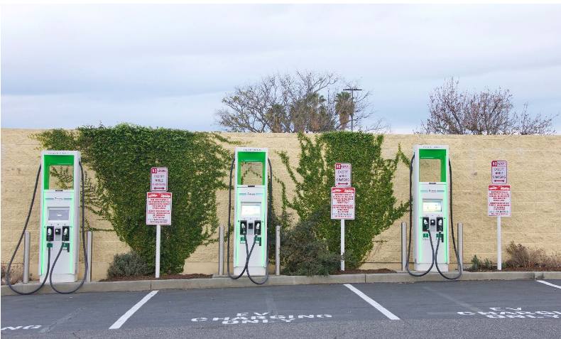
If you are involved in the regular installation of DC fast chargers (Mode 4), you will already be familiar with the significant differences between individual manufacturers’ performance characteristics and the impact on the supply side equipment, e.g., transient inrush current, harmonic distortion, leakage current and associated RCD selection.
Mode 4 Guidance
It is not possible to give standardised recommendations for RCDs associated with Mode 4 chargers – But why is this?
Whilst there has been agreement for Mode 3 charging standards in Europe, with the publication of ENIEC 61851-1 2017 and the associated changes in section 722 BS7671. That is not the case with Mode 4 charging standards, which are still coalescing. DC charger design is far more complex due to the safety issues associated with high DC voltage/current. This is reflected in the time taken to agree a revision of BSENIEC61851-23 2014 – the current designated standard for DC charging, quoted in BS7671. For example, this early standard gives general design requirements but is light on standardised test methods for checking conformity. This results in a wide variation in basic standardised performance characteristics between individual manufacturers, claiming compliance with a designated standard.
Which standard?
The current edition of BS7671 (Oct 24) clause 722.531.3.101 relating to RCD selection Note 2 states that; supplies using DC vehicle connectors to the BS EN 62196 series are under consideration. For example, the designated standard BSEN 61851-23:2014 (May 2016)* for Mode 4 DC charge points recommends, under additional requirements clause 7.6, that DC EV chargers are designed to be compatible with Type A RCDs. However, as previously stated, the standard does not provide the necessary safety testing requirements to verify compatibility between the chargepoint and upstream Type A RCDs. In practice, electrical safety design characteristics/standards (that is the guts of the charger) may be more dependent on the DC interface charging technology adopted by the vehicle manufacturer e.g., CHAdeMO (Japanese), GB/T (China), CCS 1 & 2 (North America & Europe), and Tesla (proprietary design NACS - based on North American standards). Later versions of Tesla DC chargers were supplied with CSS2 interface (compatibility with European EVs), but still NA electrical design standards. In the meantime we have to look to the basic principles of BS6761 (clause 133.1, 134.1.1 and 531.3.3) to select appropriate RCDs. Refer to the individual charge point manufacturer’s characteristics and installation recommendations e.g. note minimum RCD characteristic requirements at the quotation stage**.
* BSI Standards Development timeline: February 2026 for publication of the revised standard.
** Clause 642 (Inspection): An aid-memoire during installation planning / equipment verification.
Mode 4 chargers and RCDs
RCDs installed on the AC supply feeding the charger do not provide protection on the DC side of the charger. Shock and fault protection on the DC side is the responsibility of the chargepoint manufacturer. Conformity with the essential safety requirements is indicated by CE/UKCA marking – see Clause 642. Refer to the chargepoint manufacturer’s installation instructions.
In the event of an earth fault on the AC side, BS7671 411.3.2.4 specifies, for TT systems, a one-second disconnection time for distribution circuits > 32 A. Where RCDs are required to meet this condition due to Zs value, note the requirements of 411.5.3 R A x I ∆N ≤ 50 V. Refer to BS 7671 for full details.
The above safety requirement relies on the RCD operating within its designed specification. For example, high-frequency AC leakage currents (characteristic associated with AC/DC charger topology) are known to affect the tripping performance of Type A RCDs1: See below safety/departure from BS7671.
1 Example https://www.icrepq.com/icrepq21/216-21-slangen.pdf
Inrush / Transient currents
Depending on the design and technology employed, equipment containing high power rectifiers/inverters can produce significant transients during operation. Check with the equipment manufacturer - RCDs may require transient resistant features to prevent unwanted tripping and unnecessary equipment downtime. For example, Doepke DFL8-X CBRs incorporate a 5kA transient feature and adjustable time delay.
AC leakage current
This is the current that flows to earth during regular operation. Leakage current values are specific to the manufacturer’s design and will vary as a function of the individual chargepoint harmonics produced during various stages of charging and the supply quality (existing harmonic content). The existing standard BSENIEC61851-23 sets minimum protective conductor requirements for Class 1 equipment where touch currents exceed 3.5mA. Follow the manufacturer’s recommendations if they exceed the requirements of BS7671 543.1 - 543.7.
Unexplained RCD tripping may be the result of insufficient safety margin between the operational leakage current and the RCD sensitivity - see 531.3.2 (ii), or incorrect RCD selection i.e. RCD used outside of its design range (explained below) – see 531.3.3
Safety/departure from BS7671
Type A RCDs are calibrated/designed to detect leakage currents at the supply frequency f. The equipment contained in the DC charger produces leakage currents at frequencies >> f. Leakage currents generated at higher frequencies change the RCD tripping characteristics. In this case, clause 133.1.3 applies, and the designer must verify that the RCD provides the same degree of safety as clause 133.1.1. i.e., obtain information from the manufacturer confirming that the RCD will still function reliably when subjected to high-frequency leakage currents. Note the wording in clause 133.1.3: “Such use shall be recorded on the appropriate electrical certification specified in Part 6”.
Until recommendations are included in BS7671-722, unless otherwise stated in the chargepoint manufacturer’s installation instructions, only Type B RCDs (RCCB, RCBO, and CBR) should be used upstream of Mode 4 charge points – reference 531.3.3 (iv). Refer to the manufacturer’s operational characteristics for use in circuits containing equipment producing leakage currents > 1kHz.
RCCB or CBR?
The standards for RCDs relate to the design of the product about the person operating the RCD: BS7671 722.531.2.101 refers to BSEN 61008-1 product standard RCCBs; these are designed for use by “ordinary persons” (see BS7671 Part 2) and are limited to a maximum rating of 125A. For applications above 125A, 722.531.2.101 refers to BSEN 60947-2 CBRs, i.e., a circuit breaker incorporating residual current protection. These devices are not suitable for use by ordinary persons and must only be operated by instructed or skilled persons (electrically), e.g., installations covered by the Electricity at Work Regulations 1989.
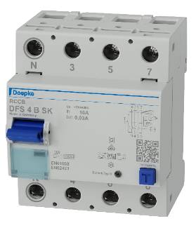
RCCB suitable for operation by ordinary persons
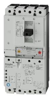
CBR suitable for operation by instructed persons
Conclusion
With any innovative technology, the “State of the art” is an important concept to consider regarding the existing requirements of BS7671 and installation advice provided by the equipment manufacturer.
Ask before acting and keep in mind the requirements of BS 7671 c133.1.1 – 3, 134.1.1, and 531.3.2 – 3.
Chaz Andrews – Technical Manager, Doepke UK Ltd
SOURCE: © 2024 - 2026 Chaz Andrews. All Rights Reserved. Doepke Tec Art 33 Mode 4 circuit protection v3 Oct 2024HL